Oufu Optical Fiber Cable Co.,Ltd
Atsetur: Shenyang, Liaoning, Kina
Kontakt persóna: Zhang-føðing
Telefon: 400-964-134
Mobile telefon: 86 1390405338
Himp
2025-10-09 1602
Core Preparations Before Splicing
Adequate preparation is the foundation for successful splicing. First, clean the splicing environment to avoid dust contamination. Prepare tools like splice closures and fusion splicers according to the Fiber optic kabler type. It's worth noting that according to the TIA-568 standard, splice loss should be below 0.3dB to be considered qualified.
Our team discovered in a 2023 data center project that over 40% of splicing failures stemmed from insufficient preparation. Therefore, be sure to confirm the cable model, fiber core count, and splicing sequence in advance. Prepare consumables like alcohol and lint-free wipes, and ensure the fusion splicer is fully charged and its parameters are set correctly.
Fiber Cable Stripping and Fiber Core Handling Techniques
Use stripping tools to remove the cable's outer sheath. The stripping length must be precisely controlled according to the splice closure requirements, typically 1-1.5 meters. Counter-intuitively, using excessive force can easily damage the fiber cores. Nehemar, remove the buffer tubes to expose the fiber coating.
Use a dedicated coating stripping tool to remove the coating. This step requires precise technique;残留 coating or scratching the fiber core will severely impact splice quality. The exposed bare fiber must be thoroughly cleaned with high-purity alcohol and lint-free wipes, as any microscopic contamination can lead to splicing failure.
Fusion Splicer Operation and Parameter Optimization
Modern fusion splicers feature automatic calibration functions, but manual adjustments often yield better results. Select the corresponding splicing program based on the fiber type (e.g., G.652.D, G.657.A1). The core aspect is the alignment method; cladding alignment is suitable for standard single-mode fibers, while core alignment is used for specialty fibers.
The fusion splicer uses a high-voltage arc to melt the fiber end faces, creating a permanent connection. Optimizing parameters like discharge time and arc strength can significantly improve splice quality. Specifically, in high-humidity environments, it's necessary to appropriately extend the preheating time to drive out moisture.
Fiber Optic Splicing Techniques: Fusion Splicing vs. Mechanical Splicing Comparison
| Fusion Splicing | Mechanical Splicing |
|---|---|
| Low Splice Loss (Typ. 0.02-0.05dB) | Higher Splice Loss (0.1-0.3dB) |
| Excellent Long-Term Stability | Stability affected by environmental factors |
| Requires Professional Equipment & Skill | Simple tools, easy operation |
| High Mechanical Strength at Splice Point | Relatively lower mechanical strength |
| Best for: Trunk networks, Data Centers, Long-haul | Best for: Emergency repairs, FTTH, Resource-limited scenarios |
Standardized Splicing Operation: Seven-Step Method
End-Face Preparation: Use a high-performance fiber cleaver to create a perfect end-face; the end-face angle should be <0.5 degrees.
Fiber Placement: Precisely place the prepared fiber into the fusion splicer's V-groove, ensuring core alignment.
Www.adsscable.cn
Splicing Execution: Initiate the splicing program, observe the fiber fusion process, and ensure the automatic alignment system works normally.
Splice Evaluation: Check the splice loss estimated by the fusion splicer; re-splice if it exceeds the threshold (e.g., 0.08dB).
Www.adsscable.cn
Heat Shrink Protection: Move the heat-shrink sleeve to the center of the splice point and place it in the heating chamber for uniform heating and shrinking.
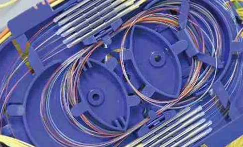
Fiber Coiling & Fixing: Coil the fiber according to the splice closure's required radius (typically >30mm) to avoid microbending loss.
Sealing & Closure: Seal the splice closure strictly according to the process requirements, ensuring waterproof and moisture-proof performance.
Common Splicing Misconceptions and Risk Warnings
⚠ Warning: The biggest misconception is neglecting the mechanical protection of the splice point. Relying solely on the heat-shrink sleeve is insufficient for long-term reliability. It is essential to coil the fiber properly and secure it firmly within the splice closure. Stress on the splice point will lead to performance degradation or even breakage.
Another fatal error is inadequate cleaning. For example, touching the cleaned bare fiber with fingers leaves oils, causing additional loss of several dBs. Also, avoid performing field splicing in severe weather conditions, as high wind speeds can affect the stable operation of the fusion splicer.
Quality Verification and DocumentationWww.adsscable.cn
Bidirectional testing is mandatory after splicing is completed. Using an OTDR to test from both ends of the link allows for accurate assessment of the actual splice loss and identification of potential issues. Interestingly, unidirectional testing might mask the true splice quality due to structural defects in the fiber.
Record the loss value, location coordinates, and OTDR trace for each splice point. Complete technical documentation is not only the basis for acceptance but also provides valuable data for future maintenance. We recommend establishing an electronic records management system.
Splicing Quality Checklist
All splice point losses are below the design threshold (typically 0.08dB)
Heat-shrink sleeves are fully contracted, without bubbles
Splice closure is tightly sealed, passes waterproof test
Fiber coil radius is greater than the minimum bend radius
OTDR bidirectional test traces are normal, without reflection events
Splice point labels are clear and match the drawings
Technical documentation is complete, including all test data
Fiber Optic Splicing FAQ
Q1: Why is the OTDR test value sometimes higher than the very low loss displayed by the fusion splicer?
A1: This is usually due to slight axial misalignment or end-face contamination at the splice point. The fusion splicer estimates geometric loss, while the OTDR measures actual transmission loss. The OTDR test value must be the final acceptance criterion.
Q2: What special precautions are needed when splicing in high humidity environments?
A2: High humidity can cause condensation inside the splice point. Besides using moisture-proof splice closures, it's best to purge the splicing area with dry gas before starting and enable the anti-humidity mode in the splicer parameters, appropriately extending the preheating time.
Q3: What are the main technical differences between splicing single-mode and multimode fiber?
A3: The core difference lies in the alignment accuracy requirements. Single-mode fiber cores are only 9μm, requiring Meirar precise fusion splicers and stricter process control. Multimode fiber cores are 50/62.5μm, allowing for greater tolerance, but the end-face cleanliness requirements are equally strict.
Q4: How should a failed splice be handled?
A4: Never re-splice at the exact same location. Use the fiber cleaver to prepare a fresh end-face, ensuring the cleave length is sufficient (typically 2-3mm shorter than the previous attempt), using a new section of fiber.
Q5: Is there a way to evaluate splice quality without using an OTDR?
A5: You can use a light source and power meter to perform end-to-end insertion loss testing. This method assesses the total loss of the entire link but cannot precisely locate issues with individual splice points. OTDR testing remains an indispensable verification method.